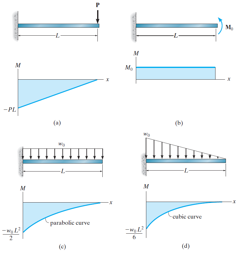
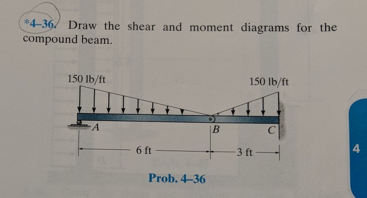
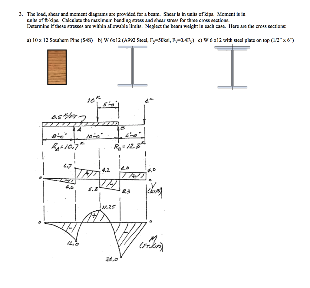
Shear and moment diagrams if the variation of v and m are written as functions of position x and plotted the resulting graphs are called the shear diagram and the moment diagram.
Floors shear and moment diagrams.
A comparison between results obtained from the hand solution and spslab spbeam software is provided to illustrate the features and capabilities of the spbeam and spslab software programs.
Free online beam calculator for generating the reactions calculating the deflection of a steel or wood beam drawing the shear and moment diagrams for the beam.
Show transcribed image text.
Use this beam span calculator to determine the reactions at the supports draw the shear and moment diagram for the beam and calculate the deflection of a steel or wood beam.
Shear and moment diagrams for a continuous beam the slope deflection method is used to determine the shear and moment diagram for the beam shown below.
These diagrams can be used to easily determine the type size and material of a member in a structure so that a given set of loads can be supported without structural failure.
The easiest and fastest way to construct a moment diagram is by using the areas of the regions in the shear diagram.
In this post we re going to take a look at shear and moment diagrams in detail.
Determining shear and moment diagrams is an essential skill for any engineer.
Shear and moment diagrams and formulas are excerpted from the western woods use book 4th edition and are provided herein as a courtesy of western wood products association.
Draw the shear and moment diagrams for the beam.
Unfortunately it s probably the one structural analysis skill most students struggle with most.
Introduction notations relative to shear and moment diagrams e modulus of elasticity psi i moment of inertia in 4 l span length of the bending member ft.
Previous question next question.
Another application of shear and moment diagrams is that the deflection of a beam can be easily determined using either the moment area method or the conjugate beam method.
4 4 area method for drawing shear moment diagrams useful relationships between the loading shear force and bending moment can be derived from the equilibrium equations.
Developing the shear and moment functions for complex beams can be quite tedious.
These relationships enable us to plot the shear force diagram directly from the load diagram and then construct the bending moment diagram from the shear force diagram.
Moment diagrams are similar to shear diagrams use them to find the location and value of the maximum positive and negative moment or the moment at any specific location.
1500 lb ft b 12 ft 6 ft this problem has been solved.
Shear and moment diagrams an ultimate guide.


